Tu154 Cockpit Tour
Author / November 2022 (4295 Words, 24 Minutes)
Captain’s panel
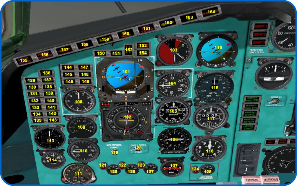
101 - Flight Director Indicator (PKP)
102 - Horizontal Situation Indicator (PNP)
103 - AOA and G-meter (AUASP)
104 - Rate-of-climb indicator VAR-30
105 - Barometric altimeter. Click the lower right knob to set the pressure
106 - Radio Magnetic indicator IKU-1 , controlled from the compass system TKS-1 and
Course system Kurs-MP-2.
107 - DME indicator IDR-1 (DME/RSBN)
108 - Indicated airspeed indicator US-I-6. The red index refers to commanded speeds for the
AT system. With Autothrottle switched off, the index is slaved to the airspeed needle
109 - Machmeter UM-1, fed from the SVS system (static pressure system)
110 - Vertical Velocity Indicator VAR-75
111 - AChS-2 clock, additional controls (like the timer) are not implemented
113 - Combined Speed Indicator KUS
114 - Outside air temperature indicator TNV-15
115 - Standby artificial horizon AGR
116 - Radio altimeter RV-5M. Mouse area in lower right allows to set DH altitude for “H”
light and the “decide” alert (indicated by the yellow bug)
117 - Altimeter UVID-15, indication in feet. This device is electric and uncoupled from the
SVS (static air pressure) system.
118 - Altimeter VM-15, SVS dependent on the SVS
119 - Warning light test button
120 - Source selector for the IDR-1 (DME). It differs a bit from the real plane. In the real
plane the indicators are independent and have their own panels for different frequencies. The KursMP system is the Russian equivalent to VOR navigation and has been added for international
flights. The switch toggles between DME-1, DME-2 and RSBN.
121-123 - Hydraulic systems 1-3 low pressure warning lights
124 - Emergency brake system low pressure warning light
125-127 - Hydraulic systems 1-3 pressure gages
128 - Emergency brake system pressure gage
129 - ЗАХОД Localizer Mode. ABSU stabilizes landing course using ILS selected on the
left KURS-MP set
130 - ЗК Heading Select Mode. ABSU stabilizes course selected using ZK bug (see HSI,
mark D).
131 - Bank Stabilization Mode. ABSU keeps constant bank
132 - NVU mode. ABSU intercepts and maintains track using NVU nav signals
133 - VOR mode. ABSU stabilizes course using VOR nav signals
134 - Marker I (outer marker). Flashes while passing the outer marker
135 - Marker II (middle marker). Flashes while passing the middle marker
136 - Bank Control Unit BKK-18 failure
137 - ГЛИСС Glideslope mode. ABSU keeps the glideslope using the ILS nav signal
138 - Autothrottle. Autothrottle is engaged
139 - Pitch Hold”. ABSU stabilizes pitch
140 - Altitude Hold Mode (H). ABSU holds altitude using pitch
141 - IAS Mode (V). ABSU uses “speed on pitch”
142 - MACH Mode (M). ABSU uses “mach speed on pitch”
143 - Marker III (Inner Marker) - not used
144 - Fuel Below 2500 KG Warning
145 - AOA Warning (stall)
146 - G Overstress Warning
147 - Lights up when the transponder is set to “hijack” (not used the sim)
148 - Lights up if Cabin Crew sends a hijack signal (not used in the sim)
149 - Overspeed Warning
150 - Left bank angle warning (33 or 15 degrees in landing config)
151 - TOGA engaged. ABSU goes around automatically
152 - Below decision height H indicator
153 - Terrain warning
154 - Right bank angle warning (33 or 15 degrees in landing config)
155 - Not in takeoff config. Flashes if takeoff procedures are not completed, namely:
• Flight control boosters are not enabled
• Nosewheel steering hyrdaulic actuator is not engaged
• Nosewheel steering set to 63 deg instead of 10
• Spoilers are extended
• Flaps are retracted
156 - “Void” pitch trim, MET Failure or MET has come to a stop or an attempt is detected
to operate pitch trim during Autopilot operation. The trim input will be ignored in this case since
the SAU (autopilot) latches on to the trim
157 - Autopilot (ABSU) - bank control failure (not implemented)
158 - Autopilot (ABSU) - pitch control failure (not implemented)
159 - Automatic TOGA failure (not implemented)
160 - Landing mode autopilot failure or glideslope deviation too big
161 - Autothrottle Control Failure - “throttle” warning (not implemented)
162 - Maximum Localizer Deviation exceeded
163 - Glideslope Deviation below 100m until DH if plane is 1 dot above glidepath
164 - Engine FIRE (not implemented)
PKP (FDI)
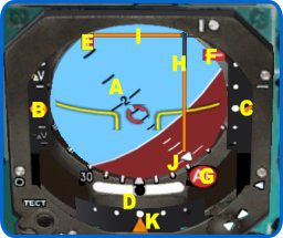 A - Artificial horizon
B - “Fast/slow” indicator - index bug moving up means that the speed is higher than
the commanded AT speed
C - Glideslope index
D - Sideslip indicator
E - Localizer flag (visible when no or nav mode is selected and being received by the
radios)
F - GS flag (visible when no glideslope is received or the FD is not engaged)
G - Vertical gyro failure flag (flag is raised when the gyro is not aligned)
H - course director arrow
I - glidepath director arrow
J - Bank angle
K - Localizer index
PNP (HSI).
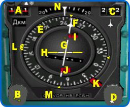 A – range scale. Not wired and not used Tu-154
B – Heading handle
C – Precise course display
D – Course handle
E - Compass scale. Can show the magnetic or gyro headings, depending on the
switch on the overhead
F – Course needle
G – Deviation needle. Shows aircraft deviation from path in various NAV modes
(ILS, VOR, NVU)
H - Glidepath needle
I - Glidepath ILS flag (visible when no glideslope is received)
J - Localizer ILS flag (visible when no loc signal is received)
K – TKS compass system flag (visible when the system is inop)
L – Heading bug (ZK)
M - Mode Indicator (SP-VOR-NVU)
N – Drift angle scale. Rolling index shows the drift angle, measured by the DISS
(doppler radar) equipment.
Overhead
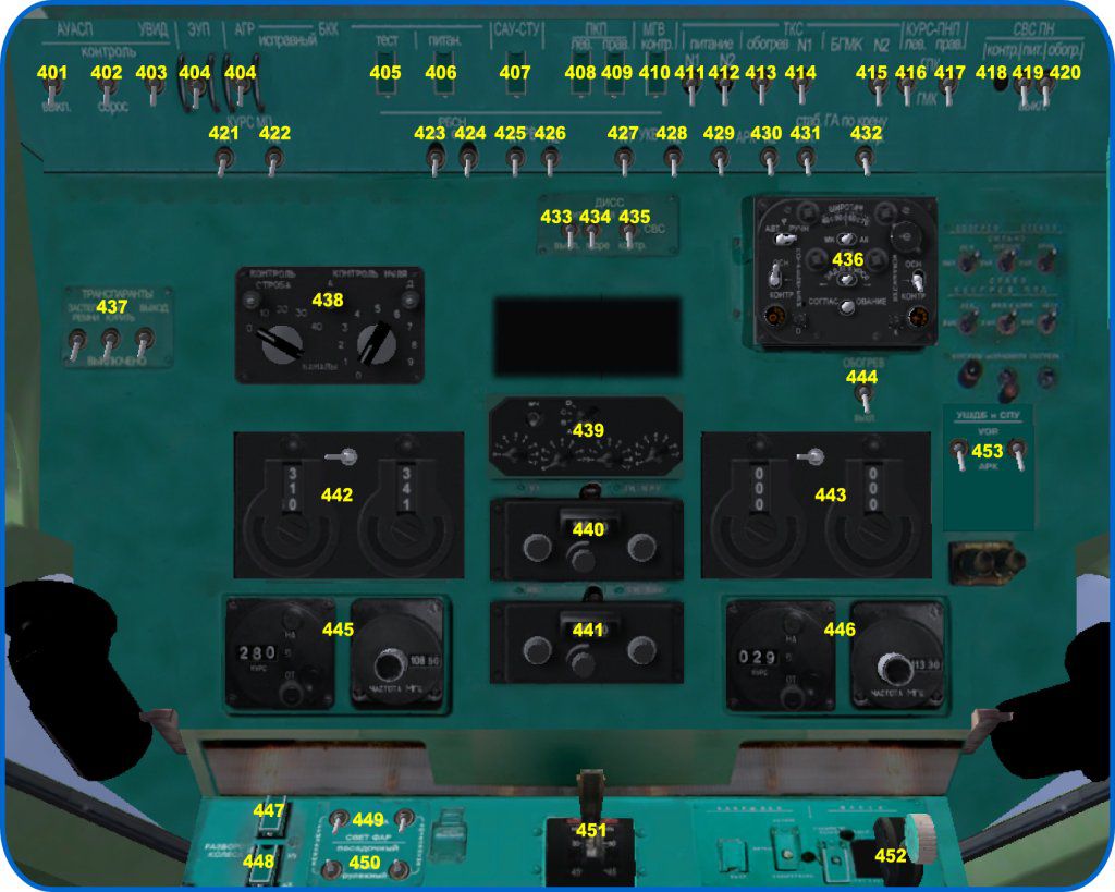
401 - AUASP system power (Angle of attack vanes and indication, G meter)
402 - AUASP check - not used in the model
403 - UVID-15 altimeter power
404 - AGR standby ADI power
405 - Clears BKK error signal and flags on the ADI
406 - BKK vertical gyro power
407 - ABSU/SAU power (autopilot and flight director)
408, 409 - Attitude gyros ADI (PKP) captain and copilot power
410 - Standby attitude gyro power
411, 412 - Lateral TKS gyros power
413 - Switch lateral gyro heating. Not implemented
414, 415 - Mag course correction switches
416, 417 - Switch HSI - gyro or gyro-mag corrected heading, captain and copilot
418, 420 - Static pressure SVS check button and heat switch. Not implemented
419 - Static pressure SVS system power
421, 422 - KURS-MP nav radios power, left and right
423 - RSBN nav system power
424 - RSBN “Ident” mode switch. Since this mode is hardly ever to be implemented in FG,
in the model this switch toggles RSBN to the VOR mode
425, 426 - RV-5M Radio altimeter power. Only the captain’s radio altimeter works in the
model
427, 428 - COM radios power
429, 430 - ADF radios power
431, 432 - CB for roll correction of the lateral gyro. Since the simulator does not implement
gyro drift, these switches are not utilized. Perhaps one day the gyro drift will be implemented…
433 - Doppler drift and ground speed measurement system (DISS) power
434 - “land-sea” Doppler switch
435 - the “Diss-SVS-check” whether the NVU will be driven by the Doppler system or the
static air pressure system alone. When NVU is on SVS uncoupled from the DISS you will need to
compute and enter the wind drift yourself.
436 - PU-11 TKS (lateral gyro) control panel
437 - Passenger signs “Exit”, “No smoking, fasten safety belts.” No idea where you can
make them in the model. Not implemented.
438 - RSBN control panel. In RSBN mode, the left handle switches tens, right one - ones (of
the channel number). If RSBN works in compatibility mode with VOR, the left knob sets
megahertz, right - kilohertz. In this mode, there is a tooltip for the frequency. The “RSBN-VOR” is
possible only in the model, in terms of realism the use of this mode is not recommended
439 - Transponder. Implemented since ver.3.0. Work under FG ver.2.10 and newest. It
support skawk mode A, C, Standby mode (selector to B) and Ground mode (selector to D).
440, 441 - COM radios. There are hotspots for fequencies. Right handle control sound
volume.
442, 443 - ADF radios. The switch on the top selects the “active-standby” frequency, the
selected frequency is highlighted with a green lamp on top. The left ADF is 1, right one is 2. There
are hotspots for control sound.
444 - Pitot heat switch. As far as I know, the effects of pitot icing are not modeled in FG
445, 446 - KURS-MP nav radio. The indicator on the left switches the bearing (not the
indicator on the HSI!), the right controls the frequency. Hotspots are availaible at the top and at the
bottom of each digit. There are hotspots for control sound.
447 - Nosewheel steering hydraulics switch
448 - Nosewheel steering angle limit (63 or 10 degrees)
449 - Landing lights extend-retract switch
450 - Landing light mode tri-pos switch - landing, off and taxi
451 - Flaps lever
452 - Gear lever
453 - Switch the USHDB needles from ADF to VOR and back
PU-11 TKS compass system
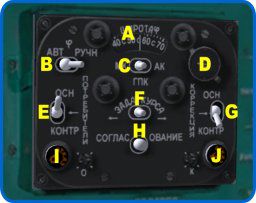 A - Latitude input
B - Automatically adjust latitude while flying. Not present on the real aircraft.
However, in the model it is possible to engage this feature. Keep on “РУЧН” (manual) for more
realism. Before flying the descent you will need to adjust the latitude to your destination.
C - Switch the correction mode of the TKS. AK AK (astrocorrection) on real aircraft
is not implemented. MK corrects the gyros to the magnetic heading, GPK uses the internal gyro
heading.
D - Latitude adjustment knob
E - switch the driving gyro TKS output from the main to the auxiliary gyro and back
F - Manual gyro adjustment
G - switch the gyro used for correction from the main to the auxiliary gyro and back
H - Quick alignment button
I, J - Main and aux gyro unit failure lamps
Center panel
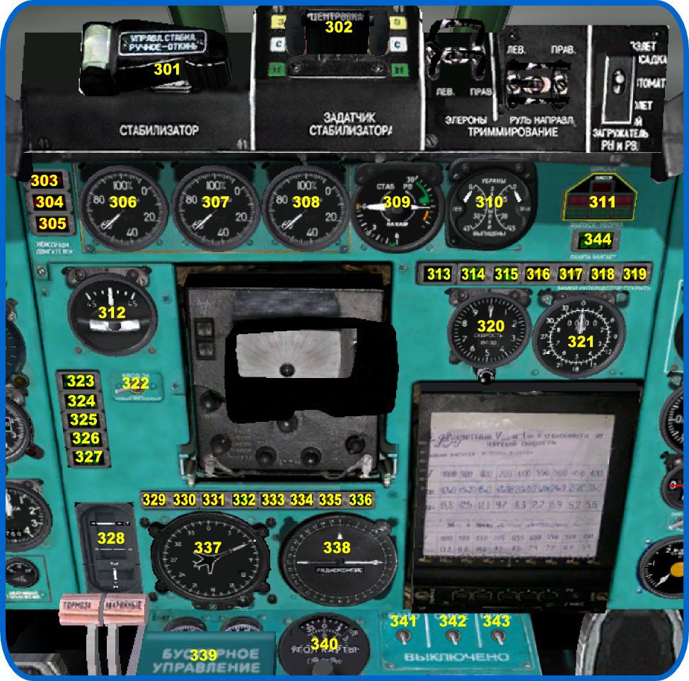
301 - Manual stabilizer control switch. To operate, open cap and press the switch
underneath - switch towards you is pitch up, switch away from you is pitch down
302 - Auto stabilizer preset
303-305 - Engine failure lamps
306-308 - Engine N2 RPM indicators
309 - Elevator/stabilizer indication. In the center of the device there is a hotspot for hints on
the current weight, CG position, Vr and Vref. The values of velocities are computed for the current
configuration
310 - Flaps indicator, left and right
311 - Gear lamps
312 - Turn coordinator EUP
313 - Placard “Stab working”. Illuminates when the stabilizer is moving
314, 315 - Placard “Flaps I”,”Flaps II”. Illuminates when the flaps left and right are moving
(the model always moves flaps in sync)
316, 319 - Placard “middle” Illuminates when the middle (in-flight) spoilers are extended
317, 318 - Placard “inner” Illuminates when the inner spoilers are extended (only possible
when the gear struts are compressed after touchdown)
320 - Groundspeed indicator USVPK. In the “air” mode shows the airspeed using the static
air pressure system(SVS), in a “ground” mode - ground speed from the DISS equipment. At the
bottom of the device there is a hotspot for mode selection
321 - Range-azimuth indicator PPDA-Sh used by the RSBN set
322 - Captain-copilot heading bug switch (the selected bug is used by the autopilot)
323, 324 - Spring loader placards. In this model, both boards are always on, the system of
loaders is not implemented
325-327 - “Trim neutral” placards. Also function as hotspots to reset trims to neutral
328 - Status of RA-56 hydraulic flight control actuators. The needles will move when the
autopilot operates the controls
329 - Placard “NVU failure”. Failures not implemented
330 - Placard “Failure of reserve MGVK”.
331 - Placard “NVU-VOR Automatic.” Illuminates when the NVU nav computer fails or
when the VOR signal used by the NVU is no longer received. Failure is not implemented
332 - Placard “Correction on”. Illuminates when the NVU is being updated from an RSBN
beacon
333, 334 - Placard “Range autonomous”,”Azimuth autonomous” Lights up when the RSBN
signal is lost
335 - Placard “DISS mem”. Lights when the DISS system is inop
336 - Placard “Change ChO” Lights up before passing an NVU waypoint
337 - USh navigator instrument. Arrow with a plane shows the main gyro heading from
TKS, movable triangular index - position of the aux gyro. Deviation arrow under the airplane arrow
shows the drift angle, measured by the DISS
338 - UShDB indicator. While the ADF arrow indicates the angle of the NDB, the VOR
mode, the opposite end of the arrow shows the current radial. VOR-ADF switch is on the overhead,
and the instrument is not slaved (rotate the compass scale using the knob on the right)
339 - Lid of the hydraulic flight control booster switches. Before take-off booster switches
should be and the lid closed
340 - “Map angle” Instrument NVU updates. There are hotspots right and left of two mobile
scales. The upper scale introduces tens of degrees, lower - ones
341 - Switch nav lights
342 - Switch beacon lights
343 - Switch instrument lights on. Lights go on throughout the cabin, including the flight
engineer panel
344 - Placard “Slats moving”. In this model slat management is slaved to the flaps, separate
slat extension is not implemented
Pedestal
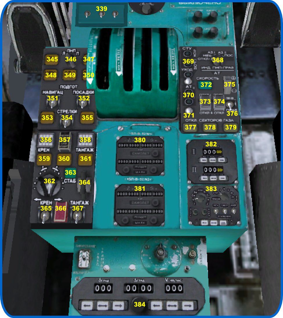
345 - Button-lamp “ZK” Autopilot heading mode, by HSI heading
346 - “L-PNP-R” selector. In VOR mode, switches the source of bearing fed to the autopilot
from the left HSI to the right one
347 - Button-lamp “Prog Reset”. Resets the autopilot to pitch and bank stab modes
348 - Button-lamp “NVU” Couples the NVU nav computer to the HSI and the autopilot
349, 350 - Button-lamp “AZ-I”, “AZ-II”. Couples the HSI and the autopilot to the left or to
the right KURS-MP nav radio set
351 - Nav needles mode (use KURS-MP as VOR receiver)
352 - Land needles mode (use KURS-MP as ILS source)
353 - Button-lamp “ЗАХОД” (localizer). Couples the autopilot bank to the ILS signal of the
left KURS-MP set
354 - Flight director needles (vertical needle only available when GS is alive and GLISS
mode is on)
355 - Button-lamp “ГЛИСС” (glideslope). Couples the autopilot pitch to the glideslope on
the left KURS-MP set
356 - Indication “Aitopilot on/off” in bank
357 - Covered button for vertical gyro alignment
358 - Indication “Aitopilot on/off” in pitch
359 - Button-lamp “M”. Mach on pitch mode
360 - Button-lamp “V”. Speed on pitch mode
361 - Button-lamp “H”. Alt capture and hold mode
362 - Autopilot turn wheel
363 - Button-lamp “Stab”. Engage or disengage the autopilot coupling (when disengaged
only the flight director will stay operative). When engaged initially will enable bank hold and pitch
hold.
364 - Pitch wheel
365 - Couple the bank channel steering or use the flight director
366 - Turbulence switch. Will toggle the steering on the autopilot to work in coarser flight
control deflections
367 - Couple the pitch channel steering or use the flight director
368 - Feed the autopilot from the left or the right HSI
369 - Lamps “computers ready” - bank, pitch stability, go-around.
370 - Lamps “autothrottle ready”
371 - AT check. Not implemented in the model
372 - Button-lamp AT speed hold (will hold the speed currently indicated)
373 - AT power switch
374 - AT “armed” indication
375 - AT speed control wheel - up is faster
376 - Switch the AT speed control bug from the left to the right airspeed indicator. In the
model the captain’s indicator is always used
377-379 - button-lamps declutch throttle levers from the autothrottle. The lamp is lit - lever
declutched. When two thrust levers are declutched AT speed hold will be disengaged. In the model,
the thrust lever control of the declutched levers is returned to the joystick axis, so preselect the right
throttle position on the joy before declutching
380, 381 - B-52 panel of the NVU nav computer
382 - V-140 panel of the NVU nav computer
383 - V-51 panel of the NVU nav computer
384 - V-57 panel of the NVU nav computer (wind drift info). Will be preset from the Doppler system or, when the NVU operates from the SVS can be used to manually enter drift
NVU panel
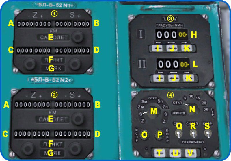 A, C - Cross-track deviation from the track(Z)
B, D - Distance to waypoint (S) at the end of the leg entered into the unit, negative is
“not reached yet” (input usually done with negative numbers)
E - Placard “airplane” Indicates that this block currently holds the active leg
F - The placard “point” Indicates that this block currently has the leg distances entered
in the lower indexes
G - Placard “beacon” Indicates that this block currently has the distances from the
waypoint to the beacon entered in the lower indexes
H - Course for the first NVU leg
I - decrease course (-) of this leg
J - Toggle I and K between coarse and fine entry
K - increase course (+) of this leg
L - Course for for the second NVU leg, same controls as H
M - select the destination for distance entries
N - LUR (turn anticipation distance). “Откл” disengages leg switching and “принуд”
forces the next leg to activate
O - Lamp “NVU ready”
P - Lamp “NVU updating”
Q - NVU power switch
R - NVU computation switch (engaged on takeoff)
S - Correction switch (when turned on, the NVU will update from the preselected
RSBN beacon)
T - Distance decrease button (-)
U - Change T and V button step distance coarse/fine
V - Distance increase button (+)
On a real plane, the smallest NVU digit is exactly a kilometer, thus the maximum possible
leg is 9999 km. In this model, you can switch the display to the scale of hundreds of meters. While
doing so, all the parameters of the NVU stay the same, only the display changes scale to be more
precise. To change the scale there is a hotspot on the B-51 panel (383), on the upper left screw.
Flight engineer panel
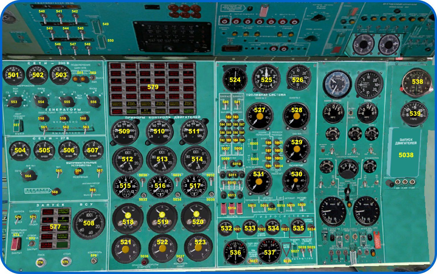
501 - AC frequency Hz
502 - AC Voltmeter
503 - AC ammeter
504 - Voltmeter for the 27V DC bus
505-507 - ammeter DC buses (left and right)
508 - APU RPM in percent
509-511 - Throttle lever position indicators (angle of detent)
512-514 - Turbine RPM indicators, N1 and N2
515-517 - Engine EGT temperature, in degrees C
518-519 - Fuel and oil pressure/oil temp combined gages
521-523 - Fuel flow meters
524 - Airspeed indicator
525 - Altimeter
526 - Vertical velocity indicator
527 - Tanks 2 fuel level
528 - Tanks 3 fuel level
529 - Ballast tank 4 fuel level
530 - Total fuel flow
531 - Tank 1 fuel level and fuel totalizer (the needle of the totalizer has C on it for “СУММА”)
532-534 - Hydraulic pressure in systems 1, 2 and 3
535 - Hydraulic pressure of the emergency brake system
536, 537 - Hydraulic fuel level (press the buttons underneath to display level)
538 - ACHS-2 clock. Additional scales and timer are not implemented
539 - Outside air temperature
540-542 - RA-56 hydraulic actuator switches in yaw
543-545 - RA-56 hydraulic actuator switches in bank
546-548 - RA-56 hydraulic actuator switches in pitch
549 - Hydraulic actuator crossfeed, not implemented on the model
550 - Stability augmentation in pitch switch
551 - Avionics power lights. If the lamps are on the respective 27V DC bus is offline and
the avionics are not powered
552 - tri-pos switch for the AC power source - APU-GPU-none. “РАП” is GPU and is always available on the model.
553,554, 555, 556, 564 - AC and DC indicator source (generators, bus from the APU/GPU, batteries)
557 - Emergency inverter. Not used on the model
558-560 - Generator failure lamps. The lamp is illuminated when the generator is offline
561-563 - Generator switches
565, 567 - AC\DC inverters.
566 - Standby inverter lamp. Not implemented in the model
568 - Lamp “DC Bus on battery”
569 - Battery master
570 - APU master switch
571 - “Dry-run/Start” APU switch
572 - APU fuel pump switch
573 - Air bleed valve from the APU
574 - Start APU push-button
575 - Stop APU push-button
576 - Warning test APU panel
577 - APU warnings
580 - Fuel pumps in tank 2 left
581 - Fuel pumps in tank 2 right
582 - Balancing light tank 2 left
583 - Balancing light 2 right
584, 588, 592 - Fuel pump lamps in tank 3 left
585, 589 - Fuel pump lamps tank 2 left
586, 590 - Fuel pump lamps tank 2 right
587,591, 595 - Fuel pump lamps tank 3 right
593 - Balancing light tank 3 left
594 - Balancing light tank 3 right
596, 597 - Light “transfer 3->2”
598, 599 - Light “transfer 4->2”
5001 - Auto tank selector indication light - “consuming from tanks 2”
5002 - Auto tank selector indication light - “consuming from tanks 3”
5003 - Auto tank selector indication light - - “consuming from tank 4”
5004 - Fuel auto transfer failure light
5005 - Transfer valve 3 -> 2 switch
5006 - Transfer valve 4 -> 2 switch
5007 - Fuel pump in tank 3 left switch
5008 - Fuel pump in tank 3 right switch
5009 - Fuel pump in tank 4 switch
5010 - Fuel pump in tank 4 (ballast)
5011 - Fuel pump lamps in tank 1 (engine feed pumps)
5012 - Fuel pump switches in tank 1
5013 - “Fuel shutoff valves open” lights
5014 - Fuel shutoff valve switches for engine 1, 2 and 3
5015 - Fuel meters power
5016 - Automatic balancing switch
5017 - Automatic balancing check light
5018 - Automatic fuel selector switch
5019 - Fuel source selector “auto/manual”
5020 - Flow meter
5021-5023 - Hydraulic systems 1, 2 and 3 low pressure warning lights
5024 - Emergency braking system low pressure warning light
5025 - Fluid level in the hydraulics tanks. Not implemented in the model
5026 - Pressurize the emergency braking system
5027 - 1 and 2 hydraulic systems crossfeed valve
5028, 5029 - Auxiliary hydraulic pumps for systems 2 and 3 (system 1 is cross-fed)
5030-5032 - EGT temperature meters switch
5033-5035 - EGT temp check
5036 - “Starter RPM too high” warning
5037 - Warning lights test
APU panel.
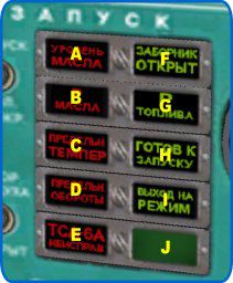 A - Oil level indicator. Not implemented
B - Oil pressure low
C - Temperature limit reached. Not implemented
D - RPM limit reached. Not implemented
E - APU failure. Not implemented
F - APU inlet open
G - Fuel pressure Ok
I - APU running and available
J - APU startup in progress
Engine warnings
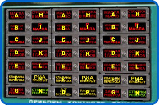 A - Oil low. Not used
B - Excess oil. Not used
C - Fuel pressure low
D - EGT too high. Not implemented
E - Bearing temp too high. Not implemented
F - Bypass valves. Illuminates when engine is on idle
G - Reverser bucket locks unlatched
H - Metal residue in oil. Not implemented
I - Oil pressure low
J - Fuel filter clogged. Not implemented
K - Halted due to EGT and TGT temperature. Not implemented
L - Dangerous vibration level. Not implemented
M - RNA covered. Lights at low RPMs
N - Reverser buckets out and engaged
O - Autothrottle clutched
P - “Release the throttles” command. Illuminates when the thrust lever is held and the AT is engaged on this engine. Not implemented
Engine start panel
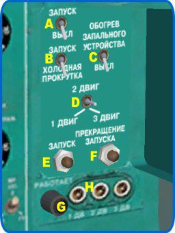 A - Main starter switch
B - “dry run/start” switch. Dry run mode is implemented, but not very realistic, and with strange bugs. Perhaps in the future, this mode will be modeled more accurately. Now I do not recommend its use
C - Iginiter Heating switch, normally used when OAT is below -5C. Not implemented in the model
D - Engine tri-pos selector
E - Start button
F - Abort spoolup button
G - Lamp “PDA is working” Lights up when the starter is activated
H - Three button “windmill start in the air.” Not implemented in the model